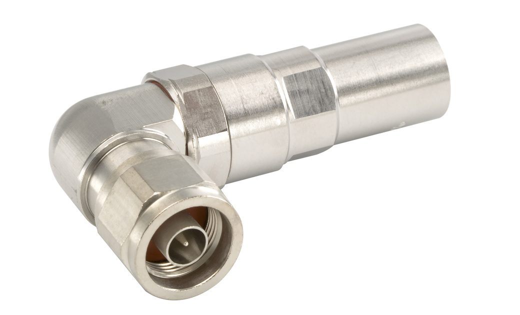
L4NR-PS
Type N Male Right Angle Positive Stop™ for 1/2 in LDF4-50A cable
Specifications
Product Classification
| Product Type | Wireless and radiating connector |
| Product Brand | HELIAX® | Positive Stop™ |
| Product Series | LDF4-50A |
| Ordering Note | CommScope® standard product (Global) |
General Specifications
| Body Style | Right angle |
| Cable Family | LDF4-50A |
| Inner Contact Attachment Method | Captivated |
| Inner Contact Plating | Gold | Silver |
| Interface | N Male |
| Mounting Angle | Right angle |
| Outer Contact Attachment Method | Self-flare |
| Outer Contact Plating | Trimetal |
| Pressurizable | No |
Dimensions
| Height | 45.97 mm | 1.810 in |
| Width | 23.62 mm | 0.930 in |
| Length | 75.18 mm | 2.960 in |
| Right Angle Length | 22.61 mm | 0.890 in |
| Nominal Size | 1/2 in |
Outline Drawing
| Click on image to enlarge. |

Electrical Specifications
| 3rd Order IMD at Frequency | -116 dBm @ 910 MHz |
| 3rd Order IMD Test Method | Two +43 dBm carriers |
| Insertion Loss Coefficient, typical | 0.05 |
| Average Power at Frequency | 0.6 kW @ 900 MHz |
| Cable Impedance | 50 ohm |
| Connector Impedance | 50 ohm |
| dc Test Voltage | 2000 V |
| Inner Contact Resistance, maximum | 2 mOhm |
| Insulation Resistance, minimum | 5000 mOhm |
| Operating Frequency Band | 0 – 8800 MHz |
| Outer Contact Resistance, maximum | 0.3 mOhm |
| Peak Power, maximum | 10 kW |
| RF Operating Voltage, maximum (vrms) | 707 V |
| Shielding Effectiveness | -110 dB |
Return Loss/VSWR
| Frequency Band | VSWR | Return Loss (dB) |
| 50–1000 MHz | 1.020 | 40.09 |
| 1000–1900 MHz | 1.040 | 34.16 |
| 1900–2200 MHz | 1.050 | 32.26 |
| 2200–2700 MHz | 1.080 | 28.30 |
| 2700–3600 MHz | 1.100 | 26.45 |
| 3600–6000 MHz | 1.119 | 25.01 |
| 6000–8800 MHz | 1.290 | -18.00 |
Mechanical Specifications
| Connector Retention Tensile Force | 889.64 N | 200.000 lbf |
| Connector Retention Torque | 5.42 N-m | 47.998 in lb |
| Coupling Nut Proof Torque | 4.52 N-m | 39.997 in lb |
| Coupling Nut Retention Force | 444.82 N | 100.000 lbf |
| Coupling Nut Retention Force Method | MIL-C-39012C-3.23, 4.6.22 |
| Interface Durability | 500 cycles |
| Interface Durability Method | IEC 61169-4:9.5 |
| Mechanical Shock Test Method | MIL-STD-202F, Method 213B, Test Condition C |
Environmental Specifications
| Operating Temperature | -55 °C to +85 °C (-67 °F to +185 °F) |
| Storage Temperature | -55 °C to +85 °C (-67 °F to +185 °F) |
| Attenuation, Ambient Temperature | 20 °C | 68 °F |
| Average Power, Ambient Temperature | 40 °C | 104 °F |
| Corrosion Test Method | MIL-STD-1344A, Method 1001.1, Test Condition A |
| Immersion Depth | 1 m |
| Immersion Test Mating | Unmated |
| Immersion Test Method | IEC 60529:2001, IP68 |
| Moisture Resistance Test Method | MIL-STD-202F, Method 106F |
| Thermal Shock Test Method | MIL-STD-202F, Method 107G, Test Condition A-1, Low Temperature -55 °C |
| Vibration Test Method | MIL-STD-202F, Method 204D, Test Condition B |
| Water Jetting Test Mating | Unmated |
| Water Jetting Test Method | IEC 60529:2001, IP66 |
Packaging and Weights
| Weight, net | 133.1 g | 0.293 lb |
Regulatory Compliance/Certifications
| Agency | Classification |
|
ISO 9001:2015
|
Designed, manufactured and/or distributed under this quality management system |
| ROHS | Compliant |
| UK-ROHS | Compliant, Compliant/Exempted |
Product Classification
| Product Type | Wireless and radiating connector |
| Product Brand | HELIAX® | Positive Stop™ |
| Product Series | LDF4-50A |
| Ordering Note | CommScope® standard product (Global) |
General Specifications
| Body Style | Right angle |
| Cable Family | LDF4-50A |
| Inner Contact Attachment Method | Captivated |
| Inner Contact Plating | Gold | Silver |
| Interface | N Male |
| Mounting Angle | Right angle |
| Outer Contact Attachment Method | Self-flare |
| Outer Contact Plating | Trimetal |
| Pressurizable | No |
Dimensions
| Height | 45.97 mm | 1.810 in |
| Width | 23.62 mm | 0.930 in |
| Length | 75.18 mm | 2.960 in |
| Right Angle Length | 22.61 mm | 0.890 in |
| Nominal Size | 1/2 in |
Electrical Specifications
| 3rd Order IMD at Frequency | -116 dBm @ 910 MHz |
| 3rd Order IMD Test Method | Two +43 dBm carriers |
| Insertion Loss Coefficient, typical | 0.05 |
| Average Power at Frequency | 0.6 kW @ 900 MHz |
| Cable Impedance | 50 ohm |
| Connector Impedance | 50 ohm |
| dc Test Voltage | 2000 V |
| Inner Contact Resistance, maximum | 2 mOhm |
| Insulation Resistance, minimum | 5000 mOhm |
| Operating Frequency Band | 0 – 8800 MHz |
| Outer Contact Resistance, maximum | 0.3 mOhm |
| Peak Power, maximum | 10 kW |
| RF Operating Voltage, maximum (vrms) | 707 V |
| Shielding Effectiveness | -110 dB |
Return Loss/VSWR
| Frequency Band | VSWR | Return Loss (dB) |
| 50–1000 MHz | 1.020 | 40.09 |
| 1000–1900 MHz | 1.040 | 34.16 |
| 1900–2200 MHz | 1.050 | 32.26 |
| 2200–2700 MHz | 1.080 | 28.30 |
| 2700–3600 MHz | 1.100 | 26.45 |
| 3600–6000 MHz | 1.119 | 25.01 |
| 6000–8800 MHz | 1.290 | -18.00 |
Mechanical Specifications
| Connector Retention Tensile Force | 889.64 N | 200.000 lbf |
| Connector Retention Torque | 5.42 N-m | 47.998 in lb |
| Coupling Nut Proof Torque | 4.52 N-m | 39.997 in lb |
| Coupling Nut Retention Force | 444.82 N | 100.000 lbf |
| Coupling Nut Retention Force Method | MIL-C-39012C-3.23, 4.6.22 |
| Interface Durability | 500 cycles |
| Interface Durability Method | IEC 61169-4:9.5 |
| Mechanical Shock Test Method | MIL-STD-202F, Method 213B, Test Condition C |
Environmental Specifications
| Operating Temperature | -55 °C to +85 °C (-67 °F to +185 °F) |
| Storage Temperature | -55 °C to +85 °C (-67 °F to +185 °F) |
| Attenuation, Ambient Temperature | 20 °C | 68 °F |
| Average Power, Ambient Temperature | 40 °C | 104 °F |
| Corrosion Test Method | MIL-STD-1344A, Method 1001.1, Test Condition A |
| Immersion Depth | 1 m |
| Immersion Test Mating | Unmated |
| Immersion Test Method | IEC 60529:2001, IP68 |
| Moisture Resistance Test Method | MIL-STD-202F, Method 106F |
| Thermal Shock Test Method | MIL-STD-202F, Method 107G, Test Condition A-1, Low Temperature -55 °C |
| Vibration Test Method | MIL-STD-202F, Method 204D, Test Condition B |
| Water Jetting Test Mating | Unmated |
| Water Jetting Test Method | IEC 60529:2001, IP66 |
Packaging and Weights
| Weight, net | 133.1 g | 0.293 lb |
| Click on image to enlarge. |
Regulatory Compliance/Certifications
| Agency | Classification |
|
ISO 9001:2015
|
Designed, manufactured and/or distributed under this quality management system |
| ROHS | Compliant |
| UK-ROHS | Compliant, Compliant/Exempted |
Documentation & Downloads
Installation Instruction
Product Specification
Warranty
Installation Instruction
Product Compliance Documentation
Product Specification
Warranty
Related Products and Accessories
Related Products
Cables
-
![]() AL4RPV-50 AL4RPV-50, HELIAX® Plenum Rated Air Dielectric Coaxial Cable, corrugated aluminum, 1/2 in, off white PVC jacket.
AL4RPV-50 AL4RPV-50, HELIAX® Plenum Rated Air Dielectric Coaxial Cable, corrugated aluminum, 1/2 in, off white PVC jacket. -
![]() AL4RPV-50R AL4RPV-50, HELIAX® Plenum Rated Air Dielectric Coaxial Cable, corrugated aluminum, 1/2 in, Red PVC jacket
AL4RPV-50R AL4RPV-50, HELIAX® Plenum Rated Air Dielectric Coaxial Cable, corrugated aluminum, 1/2 in, Red PVC jacket -
![]() HL4RPV-50 HL4-50, HELIAX® Plenum Rated Air Dielectric Coaxial Cable, corrugated copper, 1/2 in, off white PVC jacket
HL4RPV-50 HL4-50, HELIAX® Plenum Rated Air Dielectric Coaxial Cable, corrugated copper, 1/2 in, off white PVC jacket
-
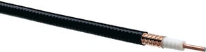
![]() 35422-25 LDF4-50A, HELIAX® Low Density Foam Coaxial Cable, corrugated copper, 1/2 in, black PE jacket, phase stabilized.
35422-25 LDF4-50A, HELIAX® Low Density Foam Coaxial Cable, corrugated copper, 1/2 in, black PE jacket, phase stabilized. -
![]() LDF4-50A LDF4-50A, HELIAX® Low Density Foam Coaxial Cable, corrugated copper, 1/2 in, black PE jacket Halogen free jacketing non-fire-retardant (General propose cable for outdoor use only)
LDF4-50A LDF4-50A, HELIAX® Low Density Foam Coaxial Cable, corrugated copper, 1/2 in, black PE jacket Halogen free jacketing non-fire-retardant (General propose cable for outdoor use only) -
![]() LDF4P-50A-42 LDF4-50A, HELIAX® Low Density Foam Premium Coaxial Cable, corrugated copper, 1/2 in, black PE jacket (Halogen free jacketing non-fire-retardant)
LDF4P-50A-42 LDF4-50A, HELIAX® Low Density Foam Premium Coaxial Cable, corrugated copper, 1/2 in, black PE jacket (Halogen free jacketing non-fire-retardant) -
![]() LDF4P-50A-43B LDF4-50A, HELIAX® Low Density Foam Premium Coaxial Cable, corrugated copper, 1/2 in, black PE jacket
LDF4P-50A-43B LDF4-50A, HELIAX® Low Density Foam Premium Coaxial Cable, corrugated copper, 1/2 in, black PE jacket -
![]() LDF4RK-50A LDF4-50, HELIAX® Low Density Foam Coaxial Cable, corrugated copper, 1/2 in, black non-halogenated, fire retardant polyolefin jacket B2ca-s1a-d1,a1 (CPR testing is conducted annually please reference the website for latest classification)
LDF4RK-50A LDF4-50, HELIAX® Low Density Foam Coaxial Cable, corrugated copper, 1/2 in, black non-halogenated, fire retardant polyolefin jacket B2ca-s1a-d1,a1 (CPR testing is conducted annually please reference the website for latest classification) -
![]() LDF4RKP-50A-42 LDF4-50, HELIAX® Low Density Foam Premium Coaxial Cable, corrugated copper, 1/2 in, black non-halogenated, fire retardant polyolefin jacket B2ca,s1a,d1,a1
LDF4RKP-50A-42 LDF4-50, HELIAX® Low Density Foam Premium Coaxial Cable, corrugated copper, 1/2 in, black non-halogenated, fire retardant polyolefin jacket B2ca,s1a,d1,a1
Structural Support, Tools & Accessories
-
![]() CPT-L4ARC1 EASIAX Plus® Automated Cable Preparation Tool for 1/2 in coaxial cable
CPT-L4ARC1 EASIAX Plus® Automated Cable Preparation Tool for 1/2 in coaxial cable -
![]() MCPT-L4 EASIAX® Manual Cable Preparation Tool for LDF4-50A coaxial cable
MCPT-L4 EASIAX® Manual Cable Preparation Tool for LDF4-50A coaxial cable


-
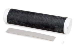
![]() 221213 Weatherproofing Kit for Connectors and Splices, includes butyl rubber and PVC tape
221213 Weatherproofing Kit for Connectors and Splices, includes butyl rubber and PVC tape

Related Products
Cables
-
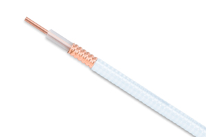
![]() AL4RPV-50 AL4RPV-50, HELIAX® Plenum Rated Air Dielectric Coaxial Cable, corrugated aluminum, 1/2 in, off white PVC jacket.
AL4RPV-50 AL4RPV-50, HELIAX® Plenum Rated Air Dielectric Coaxial Cable, corrugated aluminum, 1/2 in, off white PVC jacket. -
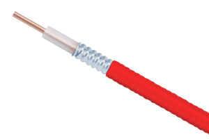
![]() AL4RPV-50R AL4RPV-50, HELIAX® Plenum Rated Air Dielectric Coaxial Cable, corrugated aluminum, 1/2 in, Red PVC jacket
AL4RPV-50R AL4RPV-50, HELIAX® Plenum Rated Air Dielectric Coaxial Cable, corrugated aluminum, 1/2 in, Red PVC jacket -
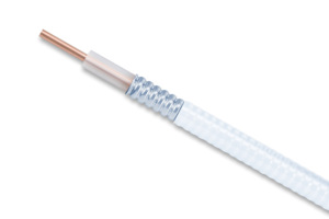
![]() HL4RPV-50 HL4-50, HELIAX® Plenum Rated Air Dielectric Coaxial Cable, corrugated copper, 1/2 in, off white PVC jacket
HL4RPV-50 HL4-50, HELIAX® Plenum Rated Air Dielectric Coaxial Cable, corrugated copper, 1/2 in, off white PVC jacket
-
![]() 35422-25 LDF4-50A, HELIAX® Low Density Foam Coaxial Cable, corrugated copper, 1/2 in, black PE jacket, phase stabilized.
35422-25 LDF4-50A, HELIAX® Low Density Foam Coaxial Cable, corrugated copper, 1/2 in, black PE jacket, phase stabilized. -
![]() LDF4-50A LDF4-50A, HELIAX® Low Density Foam Coaxial Cable, corrugated copper, 1/2 in, black PE jacket Halogen free jacketing non-fire-retardant (General propose cable for outdoor use only)
LDF4-50A LDF4-50A, HELIAX® Low Density Foam Coaxial Cable, corrugated copper, 1/2 in, black PE jacket Halogen free jacketing non-fire-retardant (General propose cable for outdoor use only) -
![]() LDF4P-50A-42 LDF4-50A, HELIAX® Low Density Foam Premium Coaxial Cable, corrugated copper, 1/2 in, black PE jacket (Halogen free jacketing non-fire-retardant)
LDF4P-50A-42 LDF4-50A, HELIAX® Low Density Foam Premium Coaxial Cable, corrugated copper, 1/2 in, black PE jacket (Halogen free jacketing non-fire-retardant) -
![]() LDF4P-50A-43B LDF4-50A, HELIAX® Low Density Foam Premium Coaxial Cable, corrugated copper, 1/2 in, black PE jacket
LDF4P-50A-43B LDF4-50A, HELIAX® Low Density Foam Premium Coaxial Cable, corrugated copper, 1/2 in, black PE jacket -
![]() LDF4RK-50A LDF4-50, HELIAX® Low Density Foam Coaxial Cable, corrugated copper, 1/2 in, black non-halogenated, fire retardant polyolefin jacket B2ca-s1a-d1,a1 (CPR testing is conducted annually please reference the website for latest classification)
LDF4RK-50A LDF4-50, HELIAX® Low Density Foam Coaxial Cable, corrugated copper, 1/2 in, black non-halogenated, fire retardant polyolefin jacket B2ca-s1a-d1,a1 (CPR testing is conducted annually please reference the website for latest classification) -
![]() LDF4RKP-50A-42 LDF4-50, HELIAX® Low Density Foam Premium Coaxial Cable, corrugated copper, 1/2 in, black non-halogenated, fire retardant polyolefin jacket B2ca,s1a,d1,a1
LDF4RKP-50A-42 LDF4-50, HELIAX® Low Density Foam Premium Coaxial Cable, corrugated copper, 1/2 in, black non-halogenated, fire retardant polyolefin jacket B2ca,s1a,d1,a1
Structural Support, Tools & Accessories
-
![]() CPT-L4ARC1 EASIAX Plus® Automated Cable Preparation Tool for 1/2 in coaxial cable
CPT-L4ARC1 EASIAX Plus® Automated Cable Preparation Tool for 1/2 in coaxial cable -
![]() MCPT-L4 EASIAX® Manual Cable Preparation Tool for LDF4-50A coaxial cable
MCPT-L4 EASIAX® Manual Cable Preparation Tool for LDF4-50A coaxial cable
-
![]() 221213 Weatherproofing Kit for Connectors and Splices, includes butyl rubber and PVC tape
221213 Weatherproofing Kit for Connectors and Splices, includes butyl rubber and PVC tape
Other Ways to Browse
