Author

Jyoti Ojha
As wireless operators increase network capacity with 5G and other technologies, they must continue to manage high rates of data traffic. Much of today’s wireless traffic can be attributed to the rapid increase in connected devices, sensors and systems being deployed throughout the enterprise.
Supporting this surge in business-centric data has become especially problematic in areas of high urban density. As city and suburban locations become more congested, the availability of suitable cell sites for antennas and other RF equipment grows scarce. As a result, more cell locations are being deployed on rooftops.
Rooftop site designs typically include antennas that are mounted close to the roof’s edge to ensure adequate coverage. In many cases, however, zoning ordinances or building restrictions force network designers to locate the antennas far from the building edges. In this scenario, antennas could face metal structures or structures with metal fasteners that create a reflected passive intermodulation (PIM) problem.
How to minimize PIM?
PIM is like active intermodulation but occurs in passive devices. It is created when two or more signals in a passive, non-linear device combine to form new, disruptive frequencies. If the new signals fall in an operator’s uplink band, they can elevate the noise floor and degrade system performance. Consequences from PIM include poor performance, dropped calls and increased power consumption. The severity of the effects depends on how far from the antenna the PIM source is. The closer the source, the more severe the effects.
Near-field PIM is generated in non-linear objects typically located in proximity to the front and back of the antennas. They include:
- Loose metal parts, such as metal shavings, nuts, bolts, and washers
- Metal cable mounting clips
- Ground bar connections
- Radio unit mounting brackets
- Antenna mounts
- Antenna pipe bracket connection
At the same time, near-field PIM can also be generated by the physical condition of these non-linear objects. For example, rust and corrosion or low contact pressure in metal-to-metal joints.
Common practices for minimizing near-field PIM include:
- Removing unneeded affixed hardware from the site
- Removing loose hardware and metal debris around the area
- Minimizing metal-to-metal junctions by using non-metal components
- Tightening all connections and regularly checking for vibration-induced loosening
- Locating antennas away from rooftop structures like air handling equipment and vents.
- Installing radios, overvoltage protection (OVPs) and other equipment behind and away from the antenna
- Maintaining and replacing any corroded components: bolts, nuts, roof flashing, etc.
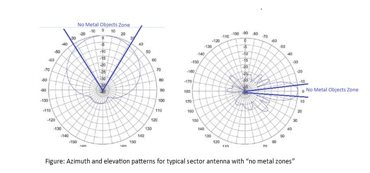
A second major type of intermodulation interference, external reflected PIM, is generated when signals from external high-power emitters near the antennas are affected by nearby corroded objects such as rusty bolts, pipes or brackets. External PIM can occur as far out as 60-100 feet in front of the antenna.
A typical rooftop antenna deployment involves panel antennas with 65-degree azimuth beamwidth and 5- to 15-degree elevation beamwidth. Designed to deliver wide coverage, these antennas are especially susceptible to external PIM. The most effective way to minimize the risk is to regularly police the site—cleaning or removing the metal objects within the antenna’s beam widths to create a “no metal zone.” Another approach is to install the antenna above the height of the building's parapet and toward the edge of the building. This provides the clearest view of the sector being served and reduces the chance of reflected PIM.
Design considerations for minimizing PIM
External PIM can be mitigated during the design and construction phase not only by creating a “no metal zone” but also having the proper spacing between each affected antenna. Studies show that antennas wider than 12 inches still need a minimum clearance of 24 inches on the back side. Repositioning the antenna farther away from another antenna clears the azimuth path, reducing the intermodulation products.
One of the issues for structural engineers is providing assurance to the rooftop building owners that the roof can withstand the additional loads imposed by these roof-mounted structures. Installations with antennas on the exterior surface of the building, penthouse, or parapet external walls may have an adverse effect on antenna-supporting structures and building components. Finding proper antenna mount options such as high eccentric antenna mount frames along with longer face width to satisfy the antenna separation requirements can be challenging. Visit CommScope’s website for more details on PIM-friendly rooftop solutions
2022 has already seen an aggressive trend to supplement free-standing urban street level cell sites with more rooftop site builds. Now—more than ever—PIM concerns are becoming prevalent. Recognition of this problem has been steadily building as the number of active and passive devices, RF and non-RF, steadily increases. Going forward, the mobile industry faces the collective challenge of developing and implementing innovative solutions to help accommodate the move to crowded rooftops while minimizing the risks of PIM.