E16V90P44
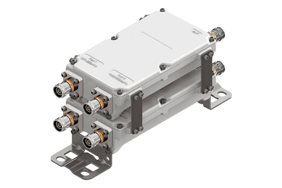
Paired 2-pak Diplexer, 380–960 MHz/1710–2690 MHz, dc pass low paired with high, with 4.3-10 connectors
Features and Benefits
- New 4.3-10 connectors for improved PIM performance and size reduction
- dc/AISG pass-through on low frequency ports for Module1 and dc/AISG pass-through on high frequency for Module2
- BTS-to-feeder and feeder-to-antenna application
- Minimal Insertion Loss
- Ultra-wideband low-band combiner
- Ultra-wideband high-band combiner
- Twin configuration
Specifications
Product Classification
| Product Type | Diplexer |
General Specifications
| Product Family | CBC426 |
| Color | Gray |
| Common Port Label | ANT |
| Modularity | 1+1-Pair |
| Mounting | Pole | Wall |
| Mounting Pipe Hardware | Band clamps (2) |
| RF Connector Interface | 4.3-10 Female |
| RF Connector Interface Body Style | Medium neck |
Dimensions
| Height | 200 mm | 7.874 in |
| Width | 111 mm | 4.37 in |
| Depth | 104 mm | 4.094 in |
| Ground Screw Diameter | 5 mm | 0.197 in |
| Mounting Pipe Diameter Range | 40–160 mm |
Outline Drawing
| Click on image to enlarge. |

Electrical Specifications
| Impedance | 50 ohm |
| License Band, Band Pass | APT 700 | AWS 1700 | CEL 850 | CEL 900 | DCS 1800 | EDD 800 | IMT 2100 | IMT 2600 | LMR 750 | LMR 800 | LMR 900 | PCS 1900 | TDD 2300 | TDD 2600 | USA 700 | USA 750 | WCS 2300 |
Electrical Specifications, dc Power/Alarm
| dc/AISG Pass-through Method | Factory set |
| dc/AISG Pass-through Path | Branch 1 | Branch 2 |
| dc/AISG Pass-through, combiner | Branch 1 | Branch 2 |
| dc/AISG Pass-through, demultiplexer | Branch 1 | Branch 2 |
| Lightning Surge Current | 10 kA |
| Lightning Surge Current Waveform | 8/20 waveform |
Electrical Specifications, AISG
| AISG Carrier | 2176 KHz ± 100 ppm |
| Insertion Loss, maximum | 0.5 dB |
| Return Loss, minimum | 15 dB |
Electrical Specifications
| Sub-module | 1 | 2 | 1 | 2 |
| Branch | 1 | 2 |
| Port Designation | PORT 1 380-960 | PORT 2 1695-2690 |
| License Band | APT 700, Band Pass CEL 850, Band Pass CEL 900, Band Pass EDD 800, Band Pass LMR 750, Band Pass LMR 800, Band Pass LMR 900, Band Pass USA 700, Band Pass USA 750, Band Pass | AWS 1700, Band Pass DCS 1800, Band Pass IMT 2100, Band Pass IMT 2600, Band Pass PCS 1900, Band Pass TDD 2300, Band Pass TDD 2600, Band Pass WCS 2300, Band Pass |
Electrical Specifications, Band Pass
| Frequency Range, MHz | 380–960 | 1710–2690 |
| Insertion Loss, typical, dB | 0.15 | 0.15 |
| Total Group Delay, maximum, ns | 10 | 10 |
| Return Loss, typical, dB | 21 | 21 |
| Isolation, minimum, dB | 50 | 50 |
| Input Power, RMS, maximum, W | 500 | 500 |
| Input Power, PEP, maximum, W | 5,000 | 5,000 |
| 3rd Order PIM, typical, dBc | -160 | -160 |
| 3rd Order PIM Test Method | Two +43 dBm carriers | Two +43 dBm carriers |
Block Diagram
| Click on image to enlarge. |

Environmental Specifications
| Operating Temperature | -40 °C to +65 °C (-40 °F to +149 °F) |
| Relative Humidity | 5%–100% |
| Corrosion Test Method | IEC 60068-2-11, 30 days |
| Ingress Protection Test Method | IEC 60529:2001, IP67 |
Packaging and Weights
| Included | Mounting hardware |
| Volume | 2.5 L |
| Weight, net | 5 kg | 11.023 lb |
Regulatory Compliance/Certifications
| Agency | Classification |
| ISO 9001:2015 | Designed, manufactured and/or distributed under this quality management system |
Product Classification
| Product Type | Diplexer |
General Specifications
| Product Family | CBC426 |
| Color | Gray |
| Common Port Label | ANT |
| Modularity | 1+1-Pair |
| Mounting | Pole | Wall |
| Mounting Pipe Hardware | Band clamps (2) |
| RF Connector Interface | 4.3-10 Female |
| RF Connector Interface Body Style | Medium neck |
Dimensions
| Height | 200 mm | 7.874 in |
| Width | 111 mm | 4.37 in |
| Depth | 104 mm | 4.094 in |
| Ground Screw Diameter | 5 mm | 0.197 in |
| Mounting Pipe Diameter Range | 40–160 mm |
Electrical Specifications
| Impedance | 50 ohm |
| License Band, Band Pass | APT 700 | AWS 1700 | CEL 850 | CEL 900 | DCS 1800 | EDD 800 | IMT 2100 | IMT 2600 | LMR 750 | LMR 800 | LMR 900 | PCS 1900 | TDD 2300 | TDD 2600 | USA 700 | USA 750 | WCS 2300 |
Electrical Specifications, dc Power/Alarm
| dc/AISG Pass-through Method | Factory set |
| dc/AISG Pass-through Path | Branch 1 | Branch 2 |
| dc/AISG Pass-through, combiner | Branch 1 | Branch 2 |
| dc/AISG Pass-through, demultiplexer | Branch 1 | Branch 2 |
| Lightning Surge Current | 10 kA |
| Lightning Surge Current Waveform | 8/20 waveform |
Electrical Specifications, AISG
| AISG Carrier | 2176 KHz ± 100 ppm |
| Insertion Loss, maximum | 0.5 dB |
| Return Loss, minimum | 15 dB |
Electrical Specifications
| Sub-module | 1 | 2 | 1 | 2 |
| Branch | 1 | 2 |
| Port Designation | PORT 1 380-960 | PORT 2 1695-2690 |
| License Band | APT 700, Band Pass; CEL 850, Band Pass; CEL 900, Band Pass; EDD 800, Band Pass; LMR 750, Band Pass; LMR 800, Band Pass; LMR 900, Band Pass; USA 700, Band Pass; USA 750, Band Pass | AWS 1700, Band Pass; DCS 1800, Band Pass; IMT 2100, Band Pass; IMT 2600, Band Pass; PCS 1900, Band Pass; TDD 2300, Band Pass; TDD 2600, Band Pass; WCS 2300, Band Pass |
Electrical Specifications, Band Pass
| Frequency Range, MHz | 380–960 | 1710–2690 |
| Insertion Loss, typical, dB | 0.15 | 0.15 |
| Total Group Delay, maximum, ns | 10 | 10 |
| Return Loss, typical, dB | 21 | 21 |
| Isolation, minimum, dB | 50 | 50 |
| Input Power, RMS, maximum, W | 500 | 500 |
| Input Power, PEP, maximum, W | 5,000 | 5,000 |
| 3rd Order PIM, typical, dBc | -160 | -160 |
| 3rd Order PIM Test Method | Two +43 dBm carriers | Two +43 dBm carriers |
Environmental Specifications
| Operating Temperature | -40 °C to +65 °C (-40 °F to +149 °F) |
| Relative Humidity | 5%–100% |
| Corrosion Test Method | IEC 60068-2-11, 30 days |
| Ingress Protection Test Method | IEC 60529:2001, IP67 |
Packaging and Weights
| Included | Mounting hardware |
| Volume | 2.5 L |
| Weight, net | 5 kg | 11.023 lb |
| Click on image to enlarge. |
| Click on image to enlarge. |
Regulatory Compliance/Certifications
| Agency | Classification |
| ISO 9001:2015 | Designed, manufactured and/or distributed under this quality management system |
Documentation & Downloads
Installation Instruction
Product Specification
Video
Filter Products – Designed for PIM Excellence

Filter Products – Designed for PIM Excellence
Warranty
Installation Instruction
Product Compliance Documentation
Product Specification
Video
Filter Products – Designed for PIM Excellence
Filter Products – Designed for PIM Excellence
Warranty
Other Ways to Browse
